6.2. Measuring groundwater flow#
6.2.1. Measuring groundwater levels#
A monitoring well is a well placed to collect (geo)hydrological and/or chemical information. After construction, a monitoring well can:
Measure the groundwater levels/heads;
Give insights into the groundwater quality;
Provide data on the local soil structure, for adequate interpretation of the measurement data.
A monitoring well is generally part of a groundwater monitoring network. Such a monitoring network consists of multiple measuring points and multiple monitoring wells, and is designed on the basis of one or multiple groundwater monitoring objectives. Different objectives can be combined in one monitoring well. Depending on the groundwater monitoring purpose, measurements are either taken over a short period of time (project-based groundwater monitoring network) or over a longer period of time (permanent or regular groundwater monitoring network). A distinction can also be made in local or regional monitoring networks. Groundwater monitoring networks in urban areas have different monitoring objectives than groundwater monitoring networks in rural areas.
Examples of groundwater monitoring objectives of regional groundwater monitoring networks are:
Determining the existing groundwater levels (groundwater regime, groundwater dynamics or groundwater stage);
Mapping the depletion of natural groundwater reserves;
Drawing up a desired ground and surface water regime;
Mapping groundwater flows (direction) and systems (watersheds);
Monitoring the changes in saline seepage for salinization and waterlevel control;
Validating and calibrating large scale (groundwater) models;
Determining (trend) changes in groundwater quality and the groundwater quantity;
Determining the effect of expanding or reducing a groundwater extraction;
Gaining insight into soil storage.
Examples of monitoring objectives of urban groundwater monitoring networks are:
Collecting basic data for various studies, for example:
drainage construction;
sewer replacement;
preparation for construction;
inventory of possibilities for disconnection and infiltration;
soil remediation;
construction site dewatering.
Accurately identifying (too) high groundwater levels in a timely manner, in order to prevent moisture problems, which could damages buildings and roads;
Accurately identifying (too) low groundwater levels at an early stage, for example to prevent foundation damage due to dry periods;
Monitoring and management of drainage systems;
Detecting sewer leaks.
Examples of monitoring objectives of project-based groundwater monitoring networks are:
Determining the effect/evaluation of project measures: including recharge and depletion;
Granting and monitoring permits.
Making a good groundwater monitoring well comes with many guidelines, which for the Netherlands can be found here. For measuring groundwater quality, guidelines on different sampling methods exist with the aim not to disturb the groundwater sample and the in-situ chemical conditions. Deep anoxic groundwater is in that sense challenging to sample.
Groundwater monitoring wells are mostly used to measure the groundwater table or head, using pressure sensors which are submersed in the groundwater in the monitoring well. As the pressure measured in the monitoring well depends on the depth of the sensor in the well and the atmospheric pressures, corrections need to made to the measured pressure in order to get the groundwater level to with respect to datum or surface level.
6.2.2. Hydraulic head#
From the study of fluid mechanics, it is known that the total energy in a fluid at a certain point consists of energy from the static pressure of the fluid, the energy from elevation and kinetic energy. The total energy of the water is called the hydraulic head, also called the piezometric head or simply head. It is the height a static water column could rise due to the energy in the fluid, and is therefore expressed in meters:
where \(h\) is the head of the water [L], \(p\) is the pressure with respect to the atmospheric pressure [M/LT\(^{2}\)], \(\gamma\) is the specific weight of the fluid [M/L\(^{2}\)T\(^{2}\)], \(Z\) is the elevation above a reference level [L], \(v\) is the flow velocity [L/T] and \(g\) is the acceleration of gravity [L/T\(^2\)]. The first term is the mechanical energy due to pressure, the second term is the energy due to elevation and the last term is the energy due to velocity. In groundwater applications, typical flow velocities are so small that the velocity head is negligible and Equation (6.3) can be reduced to Equation (6.4).
The hydraulic head can be measured using a standing pipe or piezometer. Head data obtained by piezometers is the most abundant information a groundwater engineer has at his disposal. A piezometer is a hollow tube, open to the aquifer only at the bottom shown as point A in Fig. 6.9. A piezometer measures the hydraulic head in point A, which is the sum of the pressure head and the elevation head with respect to a reference level. This reference level is often chose to be the local surface level, or a local datum, like NAP in the Netherlands. In confined aquifers the hydraulic head is higher than the top of the aquifer, in unconfined aquifers the hydraulic head is at the same level as the phreatic surface, see Fig. 6.9.

Fig. 6.9 Definition of the hydraulic head in a confined (left) and unconfined aquifer (right). (Own work)#
# Note that the code cells below is used for the website only.
Exercise 6.1
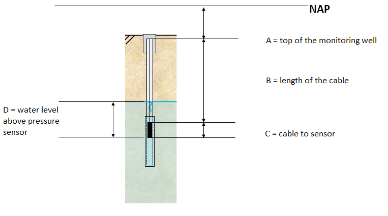
When measuring the groundwater level in a monitoring well, a pressure sensor is usually used as shown in Fig. 6.10.

Fig. 6.10 Measuring the groundwater level in a monitoring well.#
The following distances are measured:
Pressure sensor: 1136.7 cm.
Atmospheric pressure: 1078.3 cm.
Length of the cable: 2.5 m.
Distance between the cable and the pressure sensor: 6.5 cm.
Top of the monitoring well: -0.95 m NAP.
Determine the groundwater level with respect to NAP.
Answer Exercise 6.1
The groundwater level can be computed using the distances defined in Fig. 6.10:
A is equal to the top level of the monitoring well. B is equal to the length of the cable. C is equal to the distance between the cable and the sensor. D is equal to the distance between the pressure sensor and the baro pressure sensor. So the groundwater level is equal to:
6.2.3. Head in unsaturated zone#
6.2.3.1. Capillary forces#
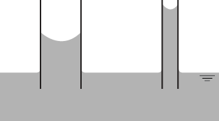
To understand the storage of water and fluxes of water in the unsaturated zone, it is important to know why water is stored above the groundwater table against the force of gravity. Soil consists of soil material and pores which can be filled with water or air. In the small pore space between the soil particles, capillary forces act on the water. Theses forces consists of adhesion forces and cohesion forces. Adhesion is the electrostatic force between the dipole water molecules and the charged soil particles which attracts water molecules to the soil particles. Cohesion is the force between water molecules because of their polarity. Water molecules at the edge of the air-water interface are pulled inwards by this force because water molecules exert a force from the inside of the water, while no force is present at the air side. This net force is called the surface tension of water which strives to reduce the exposed water surface to a minimum. The capillary force can hold the water against the force of gravity in a small cavity as shown in Fig. 6.11. The forces are in equilibrium, so the capillary force determines how high the water can rise.
In the soil, small pores have a larger capillary force than large pores so the water rises higher above the water level. When water is added to the soil, small pores fill first because the capillary forces are largest in small pores. After the small pores are filled, the larger pores start to fill as well.

Fig. 6.11 Capillary rise of water in a small cavity of different sizes. (Own work)#
6.2.3.2. Hydraulic head in unsaturated zone#
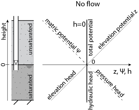
The hydraulic head is the water level in an open pipe, with the pressure at the water level equal to the atmospheric pressure. The hydraulic head consists of a pressure head and an elevation head as shown in Equation (6.5). In the saturated zone, pressure head increases with decreasing height while the elevation head decreases with decreasing height as shown at the bottom part of Fig. 6.12. Under hydrostatic conditions with no vertical flow, the hydraulic head is constant. Therefore, the sum of the pressure head and the elevation head is should be constant. In this case the reference level is equal to the phreatic surface, so the head is equal to zero everywhere.

Fig. 6.12 Hydraulic head in the saturated zone and total potential in the unsaturated zone. (Own work)#
The equation for the head in the saturated zone also holds for the unsaturated zone. The only difference is that water is present above the phreatic surface due to capillary forces. Therefore, the elevation head is positive with respect to the phreatic surface. Assuming hydrostatic condition with no water flowing, the hydraulic head should remain constant over height. This means that the pressure of the water in the pores is negative with respect to the atmospheric pressure. To avoid confusion the terms matric potential and elevation potential are used to describe the pressure head and elevation head in the unsaturated zone respectively. Equation (6.5) can be rewritten in this terms:
where \(\psi\) is the matric potential [m] and \(z\) is the elevation potential [m].
The matric potential is negative with respect to the atmospheric pressure and is often expressed in centimeters because the matric potential is generally small compared to the hydraulic head. The term suction pressure is also used, which is the absolute value of the matric potential.
The matric potential depends on the moisture content (\(\theta\)) of the soil. Soils with a larger moisture content have a smaller matric potential because the small pores are already filled with water, so part of the total matric potential is used for the water already in the soil. The soil moisture content is the ratio between the volume of water and the total volume of the ground as shown in Equation (6.7). When the soil is fully saturated, the moisture content of the soil \(\theta\) is equal to the porosity \(n\) of the soil.
where \(\theta\) is the soil moisture content [-], \(V_w\) is the volume of water [m\(^3\)] and \(V_t\) is the total volume [m\(^3\)].
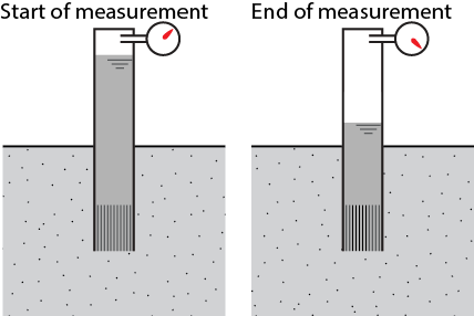
The matric pressure potential \(\psi\) can be measured with a tensiometer (Fig. 6.13). A tensiometer consist of a tube filled with water. The pressure at the top of the tensiometer is equal to the atmospheric pressure and is measured with a vacuum gauge. The water is sealed at the top and has a porous ceramic tip at the bottom which allows water to flow through slowly. As the tensiometer is placed in the soil, water is sucked out of the tensiometer by the capillary forces. This will lead to decrease in the water level in the tensiometer which leads to a partial vacuum in the tensiometer. The difference between the atmospheric pressure at the start and the pressure at the end is equal to the matric potential of the soil. The pressure is often measured in Pa, in that case the unit should be changed to meter water column (\(1\) mWc \(= \rho g h = 1000\cdot 9.81 \cdot 1 = 9810 \) Pa \(= 9.81 \) kPa).
The soil moisture content can be determined in several ways: Gravimetric analysis by weighing a soil sample before and after drying, measurement of the electrical resistance, with a neuron probe. It can also be derived from the matric potential of the soil measured with the tensiometer.

Fig. 6.13 A tensiometer.#
