6.3. Modelling groundwater flow#
6.3.1. Darcy: Groundwater flow#
A difference in hydraulic head in an aquifer, as shown in Fig. 6.9, leads to the flow of groundwater from regions with a high hydraulic head to regions with a low hydraulic head. The relationship between head difference and the flow of groundwater was first proved by Henry Darcy in 1856 with an experiment. The used setup is shown in Fig. 6.14 (Darcy, 1856).
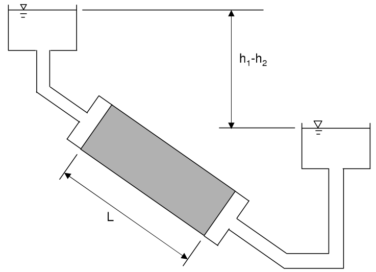
Fig. 6.14 Setup of Darcy’s experiment. (Own work)#
In this experiment, a cylinder is filled with aquifer material (such as sand) and the ends of the cylinder are connected to two reservoirs with different water levels. Water flows through the aquifer material from the reservoir with the highest water level to the reservoir with the lowest water level. With this setup, Darcy showed that the discharge (NL: debiet) through the soil column is proportional to the head difference \(h_1-h_2\) and the cross-sectional area \(A\) of the column, and inversely proportional to the length \(L\) of the soil column (Equation (6.8)).
where \(Q\) is the discharge through the aquifer material [m\(^3\)/day], \(k\) is the hydraulic conductivity [m/day], \(A\) is the cross-sectional area of the column [m\(^2\)], \(h_1-h_2\) is the head difference [m], and \(L\) is the length of the soil column [m].
To describe flow in an aquifer, the term specific discharge (NL: specifiek debiet) is used. It is the discharge per unit area of aquifer normal to the direction of the flow. Since water can flow in three directions, the specific discharge is expressed as a vector:
The components of \(\overrightarrow{q}\) in Cartesian \(x\),\(y\) and \(z\) direction may be written as follows:
where \(q\) is the specific discharge [m/day]. Equation (6.10) is known as Darcy’s law. It is an empirical formula relating the head gradient to the specific discharge vector.
6.3.1.1. The Dupuit approximation#
Darcy’s formula describes flow in three dimensions. In practice, the flow through an aquifer in the horizontal direction is several orders of magnitude larger than the flow in the vertical direction. Dupuit (1863) recognized that in many cases the vertical variation of the horizontal components of flow may be neglected, in essence reducing the mathematical description to a two-dimensional problem in the horizontal (x and y) plane. This allows many problems to be solved in a simple form that otherwise could not be solved.
With the Dupuit approximation, Darcy’s law can be written in 2 dimensions, as shown in Equation (6.11). Instead of the specific discharge, the discharge per aquifer width is used by multiplying the specific discharge by the height of the aquifer \(H\) in case of confined flow, or the height of the phreatic surface in case of unconfined flow (fig:confined_unconfined).
where \(Q_x\) and \(Q_y\) are the discharges per meter aquifer width [m\(^2\)/day] in the x- and y-direction, respectively, and \(H\) is the height of the aquifer (confined flow) or the height of the base of the aquifer to the phreatic surface [m].
6.3.1.2. Flow types#
Groundwater flow may be classified according to the spatial dimensions of the flow field, the dependence of the flow on time, and the aquifer setting in which the flow occurs. These different dimensions describe the flow field as follows:
Spatial dimension:
Flow in an aquifer can be one-, two- or three-dimensional. For relatively thin aquifers, the Dupuit approximation often produces accurate results, and one- and two-dimensional analyses are often adequate;
Time dependence:
Groundwater flow is either steady or transient. Steady flow means there are no changes in flow or head over time \(\frac{\partial}{\partial t} q =0\). Transient flow occurs when the boundary conditions change over time, leading to differences in flow and head over time;
Geologic setting:
The geologic setting may further be used to describe groundwater flow. Flow is confined when the head in the aquifer is above the impermeable top of the aquifer. The area of the flow is therefore constant. Flow is unconfined when the head is equal to the phreatic surface. This complicates calculations because the area of flow depends on the groundwater level, which in turn depends on recharge and depletion.
The focus in this chapter is on 1D and 2D steady and transient flow. In confined flow, the area of flow in the aquifer is constant, which simplifies calculations. The area of flow depends on the hydraulic head for unconfined flow. To solve the equations for unconfined flow the same approach can be taken as shown in this chapter, with the difference being that the area of flow is variable.
# Note that the code cells below is used for the website only.
Exercise 6.2
In practice, the flow in an aquifer in a certain direction can be measured with two piezometers, as shown in Fig. 6.15. If the hydraulic conductivity \(k\) (12 m/d) and the thickness of the aquifer \(H\) are known (5 m), the discharge per meter aquifer width can be calculated based on the hydraulic head measurements in two different ways.

Fig. 6.15 Measurement of flow through an aquifer.#
a) Using Equation (6.8), compute the flow, assuming a flow area with a height equal to \(H\) and a width of 1 meter.
b) Using Equation (6.10) and Equation (6.11), compute the specific discharge.
Answer Exercise 6.2a
Answer Exercise 6.2b
First, determine the specific discharge and multiply it with the aquifer height \(H\) to obtain the specific discharge:
Be aware of the units of each approach. With the first approach, we compute the discharge through 1-meter wide aquifer in m\(^3\)/d, while in the second approach, we compute the discharge per aquifer width in m\(^2\)/s. Furthermore, we can see why Darcy’s law in Equation (6.10) has a minus sign while Equation (6.8) does not. This is because the length in Eq. (6.8) is always positive, so \(\frac{h_1-h_2}{L}\) is positive for flow in the positive x-direction. In Eq. (6.10), the term \(\frac{\textrm{d}h}{\textrm{d}x}\) is negative for flow in the positive x-direction, hence the minus sign in this equation.
6.3.2. The Laplace and Poisson equation#
6.3.2.1. Laplace#
The equation for steady one-dimensional groundwater flow can be obtained by combining continuity and Darcy. Continuity requires a mass balance. Assuming water and soil to be incompressible, the difference between the inflow and outflow of a certain soil volume is equal to zero (Equation (6.12)). With a constant density, the volume balance in Fig. 6.16 can be used.
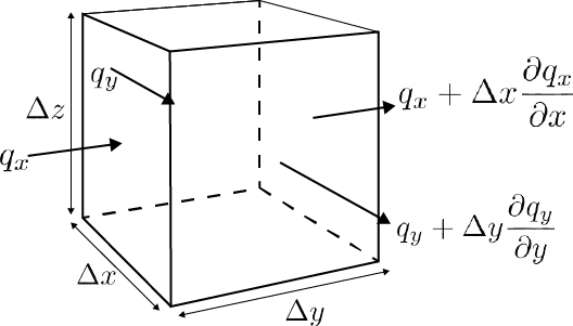
Fig. 6.16 Mass balance. (Own work)#
Substituting the fluxes in Fig. 6.16 results in Equation (6.13), which can be further simplified to (6.14):
Next, dividing by \(-\Delta x \Delta y \Delta z\) gives:
Substitution of (6.10), which defines \(q_x = -k \frac{\partial h}{\partial x}\) and \(q_y = -k \frac{\partial h}{\partial y}\), gives:
Since \(-k\) is constant, it can be taken out of the differential equation. Take the partial derivative in \(x\) and \(y\) twice and divide by \(-k\) to obtain the Laplace equation in two dimensions:
Equation (6.17) is a second-order, linear differential equation. In the following examples, the Laplace equation is used to solve some groundwater flow problems numerically. One-dimensional flow is assumed, so the terms with \(y\) are left out of the equation. The general solution of the Laplace equation is obtained by integration:
To solve this equation, the two unknowns \(A\) and \(B\) have to be solved using 2 boundary conditions defined by the considered problem.
# Note that the code cells below is used for the website only.
Exercise 6.3
The general solution provided by Equation (6.18) can be applied to several cases. Assume groundwater flow between two long waterways with different constant water levels as shown in Fig. 6.17. The water levels in the waterways are \(h_1\) and \(h_2\) respectively. The distance between the two waterways is \(L\), the height of the aquifer is \(H\) and the hydraulic conductivity is \(k\). The height of the aquifer and the hydraulic conductivity are assumed to be constant. Using the boundary conditions, the head in the aquifer can be calculated.
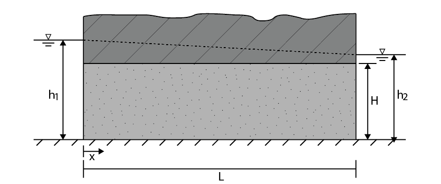
Fig. 6.17 Confined flow between two waterways with a constant head.#
a) Use the general solution (Equation (6.18)) to determine the constants A and B.
b) Substitute A and B in the general solution to obtain the formula for the head in the aquifer.
The flow between the aquifers is constant everywhere in the aquifer and is obtained by substituting the derivative of the formula obtained in question b in Darcy’s formula for flow through an aquifer (Equation (6.11)).
c) Derive the equation for this constant flow.
d) What is the direction of the flow?
Answer Exercise 6.3a
Answer Exercise 6.3b
This shows a linear decreasing relationship in hydraulic head between the two canals, independent of the hydraulic conductivity and the aquifer height.
Answer Exercise 6.3c
Answer Exercise 6.3d
In this case, \(h_1\) is larger than \(h_2\), thus \(Q_x\) is positive. This means the flow direction is in the positive x-direction from \(h_1\) to \(h_2\).
6.3.2.2. Poisson#
The same approach can be taken when recharge of groundwater \(N\) (NL: grondwateraanvulling) is present. Recharge is the extra inflow or outflow of water through the upper boundary. In case of infiltration of water into the aquifer, the recharge is positive. In the case of soil evaporation or transpiration or groundwater extraction with wells, the recharge is negative. Similar to Laplace, continuity of mass and Darcy’s law are combined:
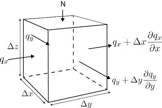
Fig. 6.18 Mass balance. (Own work)#
The continuity of mass means that the following must hold:
when including the fluxes shown in Fig. 6.18 and simplifying, this results in:
Then dividing by \(\Delta x \Delta y\) gives:
If we now substitute Darcy’s law for the flow in an aquifer (\(q_x = -k \frac{\partial h}{\partial x}\) and \(q_y = -k \frac{\partial h}{\partial y}\)) and assume that \(\Delta z\) is equal to the aquifer thickness \(H\) (for confined flow) we obtain:
Because \(-kH\) is constant, it can be taken out of the differential equation. After, taking the second derivative to obtain the Poisson equation:
In this reader we are only investigating one dimensional flow, and therefore the y-component is neglected. Integrating twice to obtain the general solution of the Poisson equation in one dimension, we obtain
When there is no areal recharge, the Poisson equation in one dimension is equal to the Laplace equation in one dimension (comparing Equation (6.18) and Equation (6.25)).
# Note that the code cells below is used for the website only.
Exercise 6.4
The solution changes when an equally distributed areal recharge is taken into account. Areal recharge is the inflow of water due to the infiltration of precipitated water into the ground. When evaporation is higher than precipitation, the value of the areal recharge is negative. Assume that the area of flow does not depend on the height of the water table, so this problem can be solved using the general solution for the Poisson equation for confined flow (Eq. (6.24)) and the same boundary conditions as in the previous example:
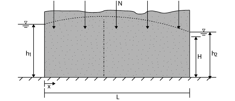
Fig. 6.19 Unconfined flow between two waterways with a constant head and areal recharge.#
a) Use the general solution (Equation (6.25)) to determine the constants A and B.
b) Substitute A and B in the general solution to obtain the formula for the head in the aquifer.
The hydraulic head is a parabolic function between the two waterways. With equal levels in the waterways, the maximum hydraulic head in the middle of the aquifer is \(\frac{NL^2}{8kH}\) above the water level of the waterways. The highest point is called the groundwater divide. Water infiltrating left of the water divide flows towards the left and water infiltrating right of the water divide flows toward the right.
The flow towards each waterway is equal to half of the total recharge if the water level in the waterways is equal. Otherwise, the flow can be calculated using the derivative of the equation obtained in question b and Darcy’s law (Equation (6.11)).
c) Compute the flow.
d) Compute the location of the groundwater divide.
e) Determine the maximum head in the aquifer.
f) Compute the discharge into both aquifers.
Answer Exercise 6.4a
Answer Exercise 6.4b
Answer Exercise 6.4c
Answer Exercise 6.4d
The location of the groundwater divide is calculated by solving the case where \(Q_x =0\) and solving for \(x\). A groundwater divide is not present when the difference in water level is too high.
Answer Exercise 6.4e
The highest head is at the location of the groundwater divide.
Answer Exercise 6.4f
The inflow to the left waterway is the flow at \(x=0\) and the flow to the right waterway is the flow at \(x=L\).
Using the equation for flow:
For \(x=0\):
For \(x=L\)
6.3.2.3. Software#
In practice, groundwater and geological conditions are too complex to apply the simplification used in the previous examples. Assuming one-dimensional horizontal flow is not adequate for many cases. For example, near wells extracting groundwater, the vertical component of flow is often considerable and cannot be neglected. The soil is often heterogeneous, the hydraulic conductivity and aquifer thickness have spatial variations. For these cases, numerical methods are often used that solve 3-dimensional groundwater flow equations. The calculations are simple but time-consuming, making the task suitable for computers. Examples of software used for groundwater flow modelling are MODFLOW and FEFLOW.
6.3.3. Transient flow#
In practice, the hydraulic head is not only a function of space but also of time due to variations in the water level, precipitation rate and pumping rate from wells. The flow of the water changes over time due to the change in head which is called transient flow (NL: tijdsafhankelijke stroming). When flow is transient, variation of storage in the aquifer has to be taken into account in the mass balance. When the head in the aquifer increases, more water is stored in the aquifer. When the head decreases, less water is stored. The mass balance is written as follows:
The change in storage over time depends on the head in the aquifer. The relationship between the change in head and change in storage volume per square meter aquifer is given by:
where \(S\) is the storativity (NL: bergingscoëfficient) which is a number between 0 and 1 [-]. The storage process is different for unconfined aquifers and confined aquifers, leading to different values of the storativity.
In unconfined aquifers, water is stored by filling the pores as the head increases. When the pores in the aquifer above the phreatic surface are completely dry, the storativity of the unconfined aquifer is equal to the porosity \(n\) of the soil. In practice, the storativity is smaller due to the presence of water in the pores above the phreatic surface. The storativity of the aquifer is also called the specific yield (NL: freatische bergingscoëfficient) \(S_y\).
In confined aquifers, an increase of the head in the aquifer does not lead to an increase in the water level. Additional water can only be stored due to compression of the water and expansion of the aquifer. The ability of aquifers to expand is much larger than the ability of water to compress, therefore the compression of water can be neglected. The storage due to expansion is small, therefore the storativity of confined aquifers is much smaller than the storativity of unconfined aquifers. The storativity of a confined aquifer is a function of the Specific storage (NL: specifieke bergingscoëfficient) \(S_s\) of the aquifer and the aquifer thickness \(H\). An aquifer with the same specific yield but twice its thickness can store twice as much water. The specific storage ranges between \(S_s\) = 10\(^{-5}\) \(\text{m}^{-1}\) and \(S_s\) = 10\(^{-3}\) \(\text{m}^{-1}\). Please note that \(S_y\) and \(S_s\) have different units. The storativity is calculated by:
Assuming 1-dimensional confined flow and taking into account variation over time, the mass balance of a section of the aquifer as shown in fig:Poisson can now be written as:
which, when dividing by \(\Delta x \Delta t\), gives
Now taking \(\Delta z = H \) and substituting in Darcy’s law (Equation (6.10)) results in the Boussinesq equation for one-dimensional flow in a confined aquifer:
Equation (6.32) is a linear partial differential equation. To solve this equation, initial conditions are required in addition to the two boundary conditions. Exact solutions are harder to obtain compared to the case of steady flow. In order to understand some basic principles of transient flow, the flow of groundwater bound by a canal with changing water levels is first considered.
6.3.3.1. Flow bound by canal#
Consider a river that fully penetrates a very long aquifer, assuming no areal recharge as shown in Fig. 6.20. Initially, the head is equal to the water level of the river (\(h=h_0\)) everywhere in the aquifer. At time \(t = t_1\) the water level in the river is raised to \(h= h_1\). The first boundary condition is the head at \(x=0\) which is equal to the water level in the river \(h_1\), \(h(x=0, t>t_1) = h_1\). The second boundary condition is the head at an infinite distance from the river \(x= \infty\) which is equal to the initial water level \(h_0\), \(h(x=\infty, t>t_1) = h_0\).
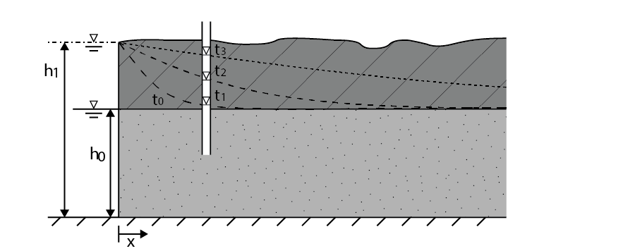
Fig. 6.20 Transient flow from a canal into a confined aquifer after increasing the water level from \(h_0\) to \(h_1\). (Own work)#
A solution to this problem was found in 1947 by Jacob Edelman Edelman (1947):
with \(erfc\) the complementary error function defined as
This function can be solved by using Laplace transformations, although it can also be solved by using the Edelman function in several programs like Excel, Matlab or Python.
The solution provided in Equation (6.33) can be used to explain how the head in the aquifer changes over time as shown in Fig. 6.20. Assume \(kH =10\) m\(^2\)/d and \(S=0.2\), which is a common value in unconfined aquifers. In this case the curves in Fig. 6.20 represent the head in the aquifer at time \(t=1, t=10 \text{ and } t=100 \) days from bottom to top. The head in the aquifer changes slowly. The storativity is much smaller when a confined aquifer is considered. If the storativity is 100 times smaller (\(S= 0.002\)), the lines in Fig. 6.20 represent the head in the aquifer at time \(t=0.01, t=0.1 \text{ and } t=1 \) day respectively. This shows that changes in hydraulic head travel faster through a confined aquifer because the storage of water is limited. The head changes slower the further away from the aquifer. Assume an increase of 0.5 meters at \(x=x_1\) at \(t=t_1\). Using Equation (6.33) it can be determined that the same head at twice the distance \(x=2\cdot x_1\) is reached after 4 times \(t=4\cdot t_1\) the time needed to obtain the head at \(x=x_1\).
Hence, increasing the water level in the river leads to a discharge of water into the aquifer which decreases over time. The discharge can be calculated by substituting Darcy’s law into the derivative of Equation (6.33), obtaining Equation (6.35). At \(t=0\) the inflow is theoretically infinite because the gradient is infinitely large, which is physically impossible. In practice, the water level never increases instantaneously, so the discharge is never infinite.
6.3.4. Vertical flow through semi-confining layers#
The previous sections focused on the horizontal flow of groundwater through aquifers. Groundwater can also flow vertically through aquitards, although the flow velocities are significantly lower compared to flow through an aquifer. The flow direction is vertical instead of horizontal because the head gradient in the vertical direction is large compared to the horizontal head gradient. Due to the flow of groundwater through the confining layers, these layers are also called semi-confining layers or leaky layers. Upward vertical flow through semi-confined aquifer occurs, for example, below lakes or rivers with a leaky layer at the bottom, or below polders where the water level is fixed. The hydraulic head in a confined aquifer can be larger than the hydraulic head of an aquifer on top due to the infiltration of groundwater into the confined aquifer at a higher elevation at a large distance, as shown in fig:GW_processes_hydrocyclegroundwater.
The specific discharge through a semi-confining layer \(q_z\) [m/day] with hydraulic head \(h_1\) in aquifer 1 and hydraulic head \(h_2\) in aquifer 2 as shown in Fig. 6.21 can be computed with Darcy’s law as:
where \(k_v\) is the vertical hydraulic conductivity [m/day] and \(H_v\) is the thickness of the semi-confining layer [m]. Aquifers are numbered top to bottom and the z-axis points in the upwards direction. The vertical hydraulic conductivity and the thickness of the semi-confining layer together determine the resistance (NL: weerstand) to flow of the layer. Therefore the resistance \(c\) with dimension time [day] is used.
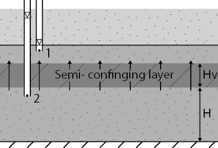
Fig. 6.21 Vertical flow through a semi-confining layer due to a hydraulic gradient. (Own work)#
6.3.4.1. Seepage into polders#
A polder is a low-lying area where the groundwater is artificially lowered with drainage and pumps as shown in Fig. 6.22. The lower phreatic groundwater level leads to upward flow of groundwater into the polder, which is called seepage. The specific discharge through the semi-confining layer is calculated with Equation (6.36). The outflow of water through the semi-confining layer leads to flow in the aquifer. The mathematical description of the flow in the aquifer due to seepage is the same as the flow in an aquifer due to areal recharge \(N\). The only difference is that the areal recharge is positive when the flow is downwards, while the seepage is positive when the flow is upwards. Equation (6.24) can be rewritten by substituting \(N\) by \(-q_z\) as defined by Equation (6.37).
When the water level in the top aquifer does not depend on \(x\), this can be rewritten as:
with \(\lambda\) the leakage factor (NL: spreidingslengte) [m]. The differential equation above is a second-order, linear, homogeneous ordinary differential equation known as the modified Helmholtz equation. The general solution is:
Again, A and B are constants to be determined from the boundary conditions.
The flow at \(x=3\lambda\) is only 5% of the flow at \(x=0\). Thus 95% of the water that flows from the canal in the aquifer is discharged into the polder within a distance of \(3\lambda\). Similarly, the difference between the head in the aquifer and the head in the polder reduces from \(h_0-h^*\) at the canal (\(x=0\)) to only \(0.05(h_0-h^*)\) at \(x=3\lambda\).
# Note that the code cells below is used for the website only.
Exercise 6.5
Let us assume one-dimensional flow from a canal into a polder as in Fig. 6.22. The aquifer is semi-confined and semi-infinite and is bounded on the left with a fully penetrating canal with water level \(h_0\). The water level in the polder is fixed at \(h^*\). At a large distance from the canal, the water level in the aquifer is equal to the water level in the canal. The following boundary conditions are used:
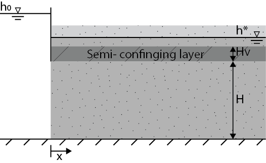
Fig. 6.22 Flow from a canal into a polder.#
Use these boundary conditions to compute the discharge into the aquifer.
Answer Exercise 6.5
Step 1
Application of the second boundary condition in the general solution (Eq. (6.40)) gives:
Step 2
Application of the first boundary condition gives
Step 3
Substitution in the general solution gives an equation for the head in the aquifer \(h\):
Step 4
The discharge into the aquifer is computed by taking the derivative of and substituting it into Darcy’s law:
6.3.5. Flow towards a well#
6.3.5.1. Steady flow#
Groundwater is often used for the production of drinking water and for irrigation. A well is used to extract this water from an aquifer. It consists of a hollow tube, which is open to the aquifer, and a well pump to extract the water. The hydraulic head in the well decreases to \(h_0\) due to the pumping of groundwater, which leads to a hydraulic gradient between the well and the surrounding aquifer. The hydraulic gradient in the aquifer leads to flow of water towards the well as shown in Fig. 6.23. In an unconfined aquifer, the water level depends on the distance from the well, and flow is 3-dimensional and radial symmetric if there are no other wells or waterways in the near vicinity. To simplify calculations, it is assumed that the well screen is placed in an confined aquifer so that the flow can be approximated as 2-dimensional.
Usually pumping rates are not constant and vary across the day and the seasons. Hence, the flow is transient, meaning the head in the aquifer around the well changes over time. Groundwater extractions may lead to conflicts with other groundwater applications and lowering the hydraulic head may lead to land subsidence.
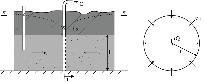
Fig. 6.23 Flow towards a well. (Own work)#
# Note that the code cells below is used for the website only.
Exercise 6.6
As shown in the right part of fig:Flow_towards_well, the hydraulic gradient at a certain distance \(r\) from the well leads to a specific discharge according to Darcy.
where the distance from the middle of the well \(r\) is used instead of distance \(x\). The specific discharge is in the direction of the well everywhere at distance \(r\) from the well, so the total flow towards the well can be calculated by multiplying the specific discharge by the area of a cylinder with radius \(r\) and height \(H\). Be aware that the specific discharge \(q_r\) is positive when water flows away from the well, and negative when flowing towards the well.
a) Rewrite and integrate this equation. Use the fact that the hydraulic head at the edge of the well is equal to the water level in the well.
b) The boundary condition at the edge of the well is used to determine \(C\). The edge of the well is at a distance equal to the radius of the well screen from the origin. Use this to obtain an expression for \(C\).
c) Substitute the expression you found for \(C\) into the integrated equation from question a. Rewrite to obtain an expression for \(h_r\).
d) Assume a well with a radius of 0.3 meter placed in a confined aquifer. The head in the aquifer is equal to zero prior to pumping, and the product of \(kH\) is equal to 100 m\(^2\)/d. The well starts pumping with a discharge of 20 m\(^3\)/day. After a certain time the water level in the well does not change and steady flow can be assumed. The head in the well is equal to -0.4 meter. What is the hydraulic head in the aquifer at a distance of 100 meter?
e) At what distance is the head equal to -0.2 meter?
Answer Exercise 6.6a
Answer Exercise 6.6b
In this case we have \(r=r0 \rightarrow h = h_0\):
Answer Exercise 6.6c
Substitution gives:
The discharge of a well and the head in a well are relatively easy to measure and the radius of the well is known. Rewrite to obtain a solution for the head in the aquifer at a distance \(r\) from the well.
with \(Q\) the discharge of the well [m\(^3\)/day], \(k\) the hydraulic conductivity of the soil [m/d], \(H\) the thickness of the aquifer [m], \(r\) the distance from the well [m] \(r_0\) the radius of the well [m] and \(h_0\) the head in the well.
Answer Exercise 6.6d
The head at a distance r=100 m is calculated with:
Answer Exercise 6.6e
To calculate the distance at which the head is equal to -0.2 meter, rewrite the equation.
6.3.6. Fresh and salt water#
In most cases, groundwater eventually discharges into rivers or oceans. In coastal aquifers, freshwater starts to float on top of salty seawater in the aquifer. The salty groundwater extends far inland, which is called saltwater intrusion. Intrusion does not necessarily mean the movement of water, it could also mean the presence of saltwater in equilibrium. Saltwater can be present far inland and could lead to problems for agriculture and drinking water production. Salt groundwater can be found almost everywhere in the Netherlands, although at a larger depth further away from the coast, while in the west of the Netherlands the shallow groundwater is already brackish.
The density of salt water is higher than the density of freshwater because salt is dissolved in the groundwater. The density of freshwater is \(\rho \approx 1000\) kg/m\(^3\) while the density of salt seawater is around \(\rho \approx 1025\) kg/m\(^3\). The freshwater therefore floats atop the salt water under normal circumstances and forms a so-called freshwater lens (NL: zoetwaterlens) on top of the salt water. The fresh water originates from precipitation and flows through the aquifer, eventually discharging into the sea as shown in fig:GW_processes_hydrocyclegroundwater. The saltwater and freshwater are mixed in the transition zone between salt and freshwater.

Fig. 6.24 Intrusion of seawater into an aquifer. (Own work)#
It is important to know the location freshwater lens for agriculture and drinking water production. Using some simplifications, the Badon Ghijben-Herzberg principle (De Vries, 1994) can be used to describe the shape of the freshwater lens as shown in Fig. 6.24. Steady-state is assumed with a hydrostatic equilibrium between the fresh and salt water. The transition from fresh to salt water is instantaneous, so no transition zone is present.
# Note that the code cells below is used for the website only.
Exercise 6.7
Using the aforementioned Badon Ghijben-Herzberg principle and assumptions for the freshwater lens as shown in fig:Seawater,
a) Derive an expression for the relationship between the freshwater depth below sea level and the height of the freshwater above sea level.
b) The groundwater table under the farmer’s field is 0.8 meter above main sea level. Calculate the total thickness of the freshwater lens.
Answer Exercise 6.7a
Step 1
In this case, the pressure in point A in the salt water is equal to the pressure in point B in the freshwater as shown in fig:Seawater.
Step 2
with \(\rho_f = 1000\) kg/m\(^3\) and \(\rho_s = 1025\) kg/m\(^3\) this can be rewritten to:
So the freshwater is 40 times as deep below sea level as the height of the fresh water above sea level. The height of the top of the freshwater lens above sea level can therefore be used to approximate the total depth of the freshwater lens.
Answer Exercise 6.7b
The thickness of the freshwater lens under the field is thus 32 m. The total thickness of the freshwater lens is then 32 + 0.8 = 32.8 m.
6.3.7. Modelling the phreatic groundwater level#
Because the phreatic groundwater level is affected by many spatially strongly varying conditions, predicting/modelling it is challenging. A basic analytical approach was developed by Helling and de Zeeuw. It requires some monitoring data to calibrate the 2 calibration factors: the drainage factor and the storage coefficient. Having set those allows to predict the groundwater level using projected evaporation and precipitation data. Please note that when there are changes in the environment the model needs re-calibration. For example if land coverage change, or if local surface water level changes.
Hellinga-de Zeeuw started with a simple equation to describe the discharge:
With:
\(q\) |
Discharge intensity |
[m/day] |
\(\alpha\) |
Drainage factor |
[1/day] |
\(\mu\) |
Storage coefficient (porosity – soil moisture at field capacity) |
[-] |
\(h\) |
Head difference |
[m] |
and a water balance:
With:
\(P\) |
Precipitation |
\(E\) |
Evaporation |
\(q\) |
Discharge intensity |
\(dt\) |
Time step |
\(\mu\) |
Storage coefficient |
\(dh\) |
Change in groundwater level |
This is a first order inhomogeneous differential equation, for which the solution can be determined in two steps; first the general solution for the homogeneous part, and then the solution for the inhomogeneous part. The general solution for the homogeneous part reads:
Then vary the constant to determine \(C\):
We need an initial value to determine \(A\). So at \(t=0\) we know that \(h_{(t)}=h_{0}\), thus:
And with \(q=\alpha \mu h\):
