Free body diagrams#
This subject allows draw a free body diagram of a structure or part of a structure.
Theory#
Free body diagram of entire model#
Before you can draw a free-body diagram, you’ve to know how our structures are modelled. Read chapter 4.1.5 of the book Engineering Mechanics Volume 1 [Hartsuijker and Welleman, 2006].
In the free body diagram of an entire model, all support are replaced by (potential) support reaction. Read chapter 4.3 of the book Engineering Mechanics Volume 1 [Hartsuijker and Welleman, 2006] for which types of support exist and which support reactions those support exert on the model.
An example model is shown in model.
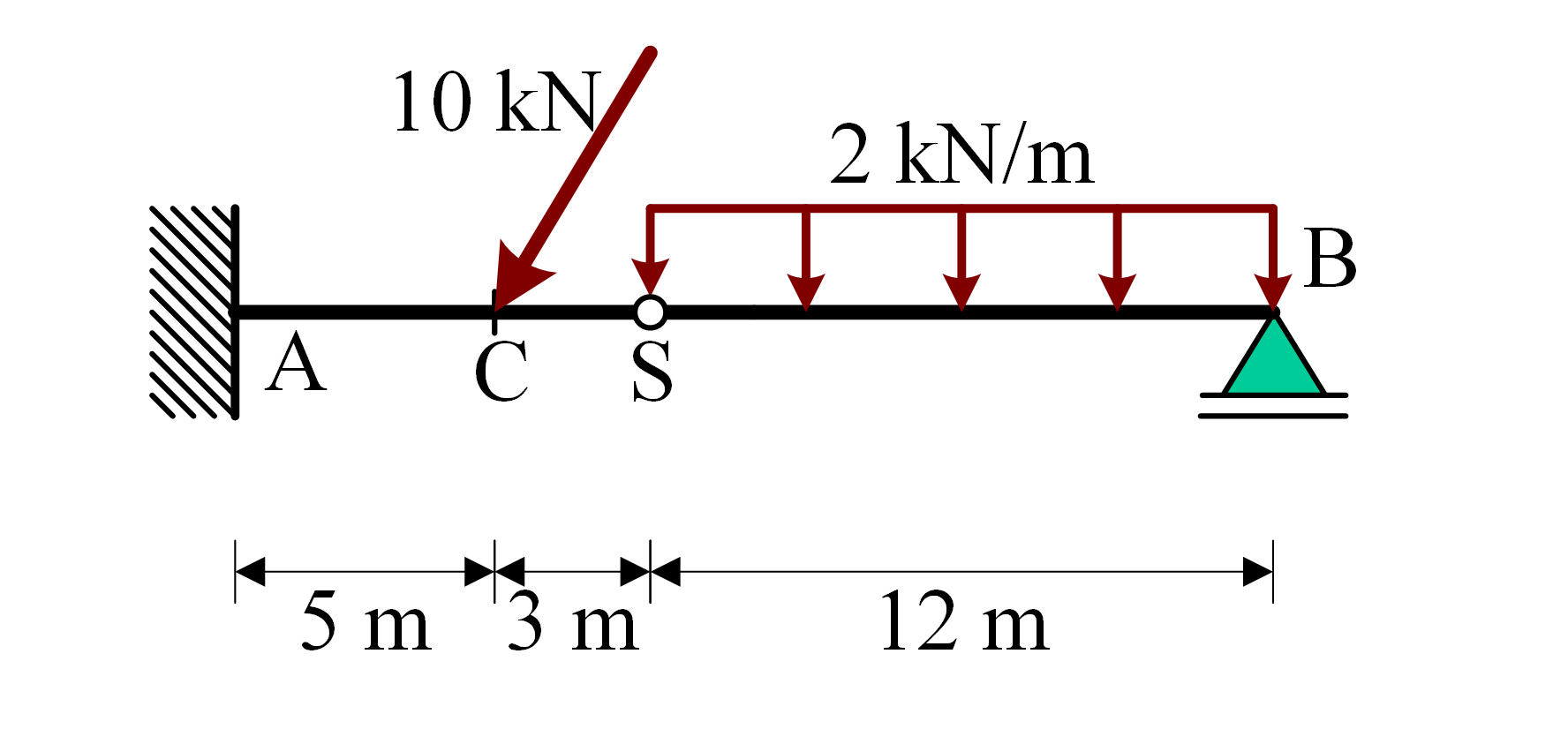
Example model#
In the free body diagram of an entire model, all support are replaced by (potential) reaction forces. The direction and size of reaction forces might not be known on beforehand. Therefore, the reactions force are indicated symbolically and the direction is assumed in the free body diagram.
The free body diagram of the entire example model is shown in FBD.
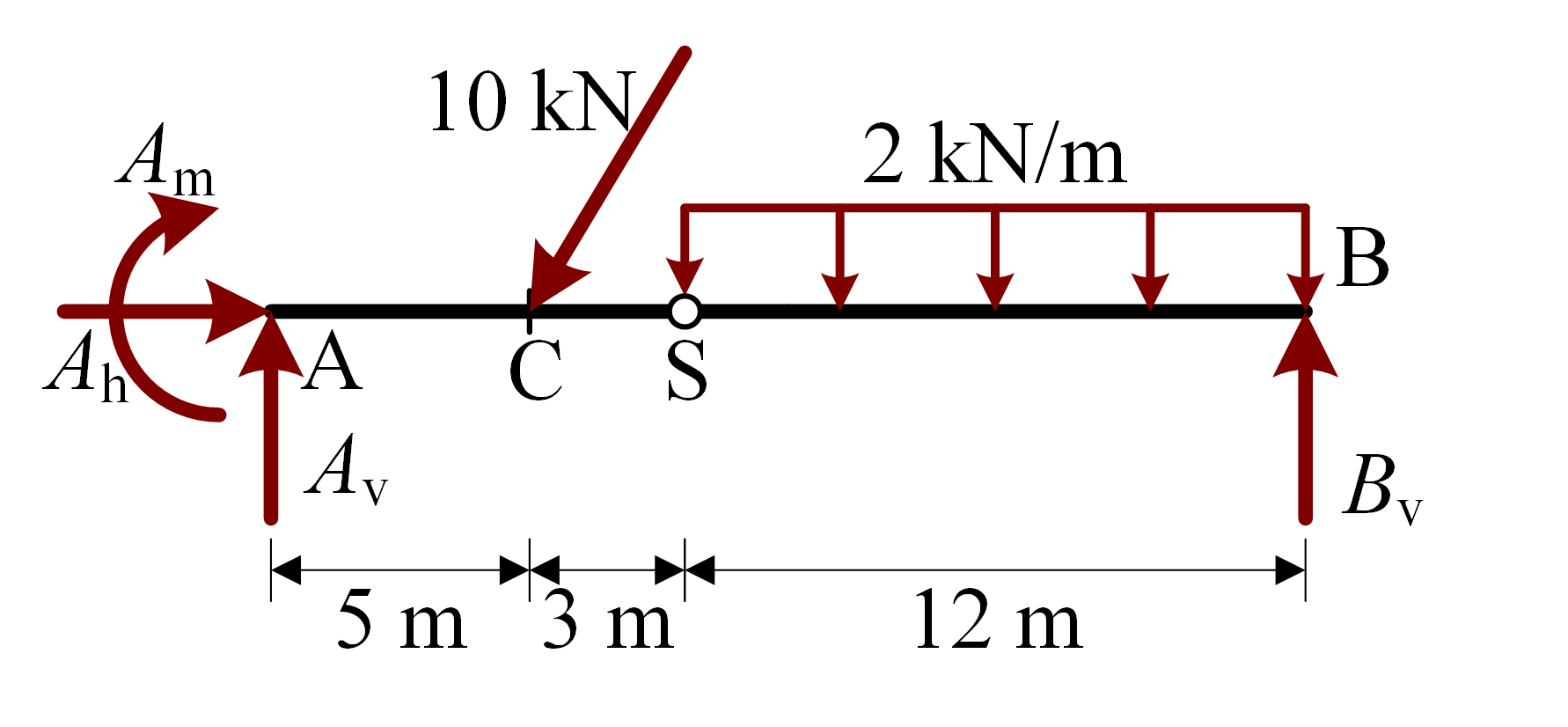
Free body diagram of the entire example model#
Free body diagram of a hinged part of a model#
In the free body diagram of a hinged part of a model, a cut is made at the hinge, showing the (potential) interaction forces at the hinge. Read chapter 4.2.1 of the book Engineering Mechanics Volume 1 [Hartsuijker and Welleman, 2006] for which interaction forces are exerted on the model. These forces are the same as the normal and shear forces at that point in the structure. As with the reaction forces, the direction and size of the interaction forces might not be known on beforehand. Therefore, the interaction force are indicated symbolically and the direction is assumed in the free body diagram.
The free body diagram of the right hinged part of the example model is shown in FBD_hinged.
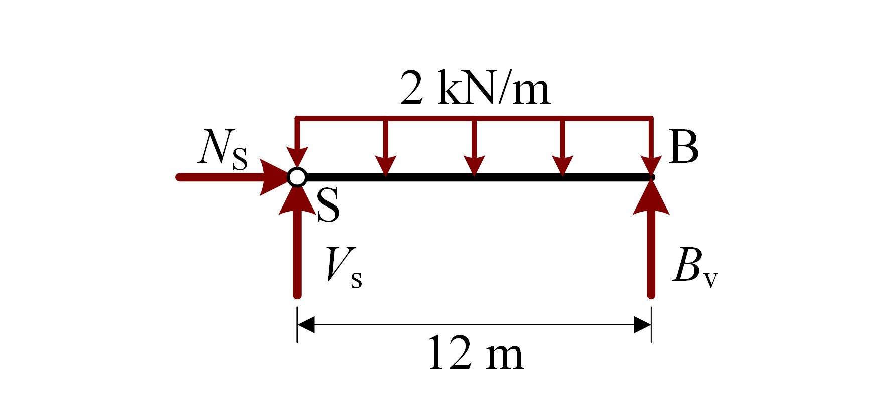
Free body diagram of the right hinged part of the example model#
Free body diagram of a part of a model#
In the free body diagram of a part of a model, a cut is made at the any arbitrary point, showing the (potential) forces and couples in the elements. Read chapter 4.2.2 of the book Engineering Mechanics Volume 1 [Hartsuijker and Welleman, 2006] for which interaction forces are exerted on the model. These interaction forces are the same as the normal- and shear forces, and the bending moments at that point in the structure. Again, the direction and size of the interaction forces might not be known on beforehand. Therefore, the interaction force are indicated symbolically and the direction is assumed in the free body diagram.
The free body diagram to the right of a cut just left of point \(\text{C}\) of the example model is shown in FBD_part.
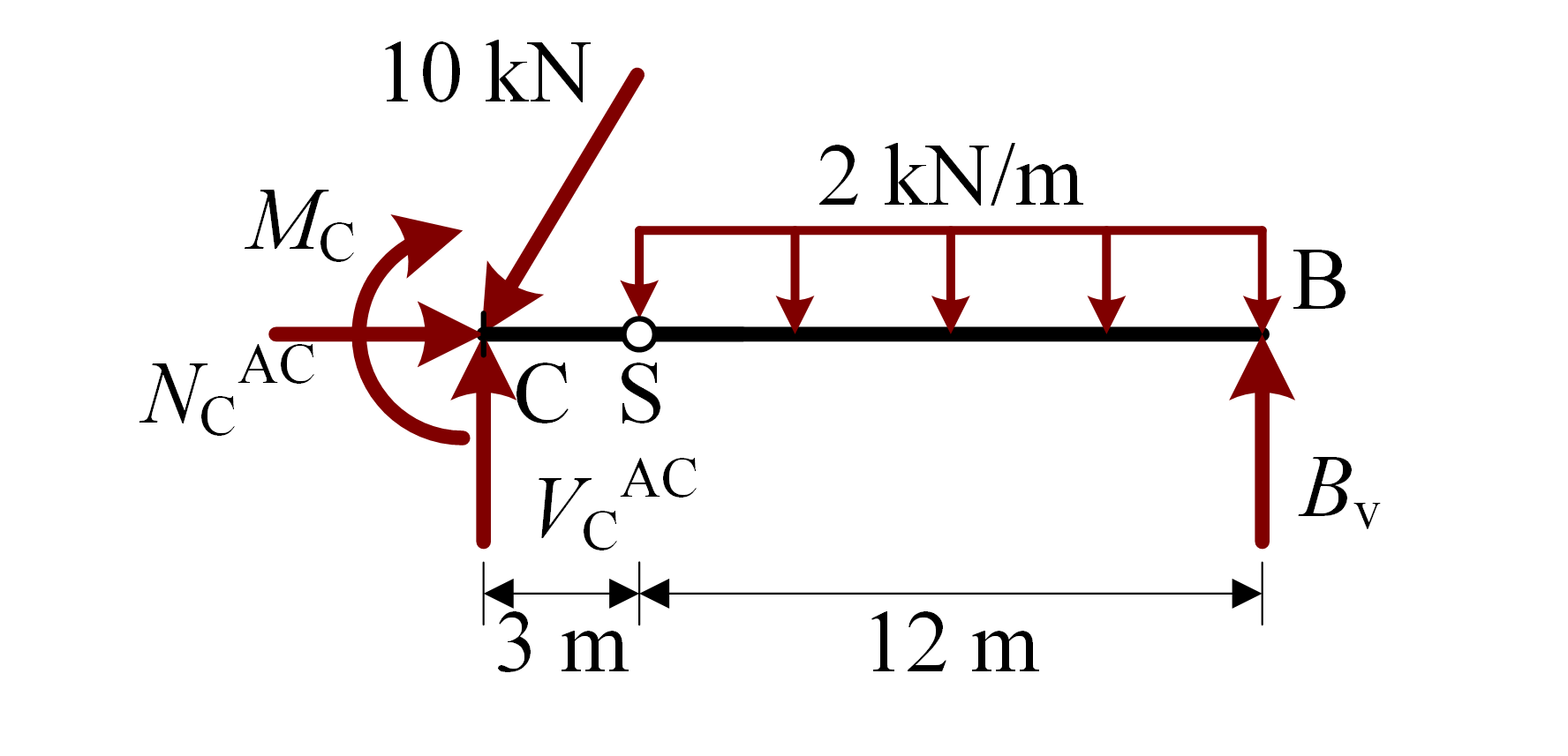
Free body diagram to the right of a cut just left of point \(\text{C}\) of the example model#
A cut can also be made such that only a single point is left. In that case you can draw the free body diagram of this single point.
The free body diagram of point \(\text{B}\) of the example model is shown in FBD_point

Free body diagram of point \(\text{B}\) of the example model#
Free body diagram of a part of a cable#
“Cables are line elements in which the resistance to bending is so small that it can be ignored. A fully flexible cable cannot transfer bending moments nor transverse forces. The force flow occurs entirely via normal forces, namely tensile forces. … Cables do not have their own shape – they adapt to the load. Here, we assume that the axial stiffness of the cable is infinite. Therefore the cable has the same length before and after loading. The shape of the cable and the cable forces can then be deduced directly from the equilibrium equations. “ [Hartsuijker and Welleman, 2006]
An example cable model is shown in model-cable.
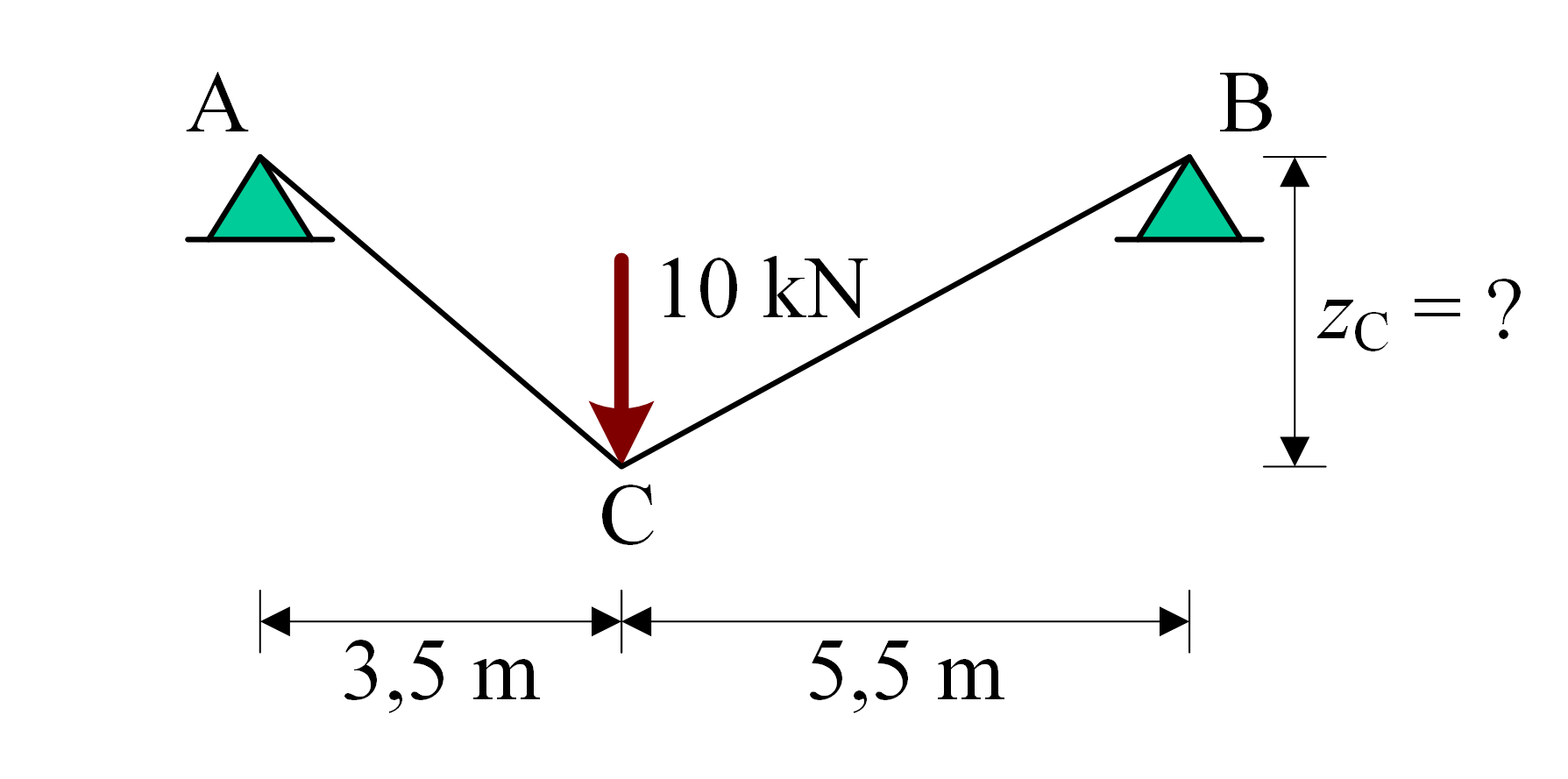
Example cable model#
As only normal forces are present, the free body diagram of a part of cable, only shows the (potential) normal force at a (potentially unknown) location.
The free body diagram to the left of a cut just right of point \(\text{C}\) of the example cable model is shown in FBD_cable.

Free body diagram to the left of a cut just right of point \(\text{C}\) of the example cable model#
Practice material#
…